Output Devices
Assignment:
For this week my assignment is to add a sensor to a micro controller to design and program it.
My Sensor Device:
My idea for my board is to have a sonar and two LEDs one red and one blue. The Ultrasonic sonar sensor is used to sensor different objects and the LED will blink blue if it sensor is working something and red if it not.
Tools needed:
1- Eagle Software
2- Cirquoid (milling machine) and Cirq Wizard
3- Soldering Equipments
4- Copper Boards
5- Electronic Components
The Sonar board that I used called “Board” from fabacademy.org website.
The “Board”
The Components needed are:
1- attitiny 45
2- HC-SRO4 (4 header pin)
3- 10 k resistors
4- ISP (3x2)
5- Capacitors 1uf
6- FTDI
Extras
7- two resistors 399 Ohm
8- LED blue
9- LED red
Making the board:
I used the eagle software as in week 10 for schematic and connecting the components together and find the optimum design of my board using the auto-router.
My design after using auto router
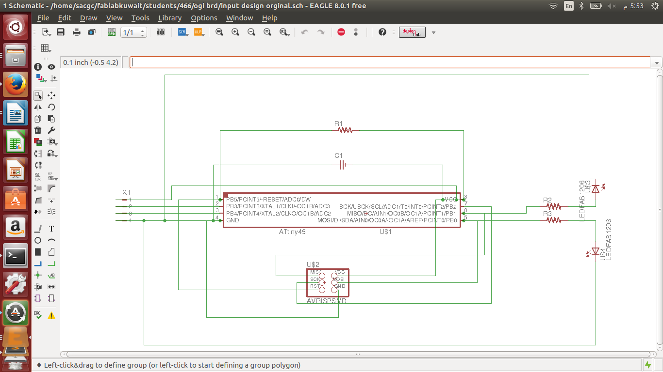
The Schematic Diagram
Then I convert my file to cmp for milling using the cam processor in eagle.
After testing and fining the right depth (Z-Axis) as in week 10 I milled my board using Cirquoid. After milling, I started soldering the components into the copperboard.
My design
4 header pin to install the sonar
Once the soldering is done then we have to program the sonar and LED to see if it works.
#include <Ultrasonic.h>
Ultrasonic ultrasonic(2,3); // (Trig PIN,Echo PIN)
int Range;
int dist;
int LED1 = 0; // LED1 Pin
int LED2 = 1;
void setup() {
pinMode(LED1, OUTPUT);
pinMode(LED2,OUTPUT);
dist = 30;
}
void loop()
{
Range = ultrasonic.Ranging(CM);
if (Range < dist)
{
digitalWrite(LED1,HIGH);
digitaWrite(LEDD2,LOW);
}
else if (Range > dist) {
digitalWrite(LED1, LOW);
digitalWrite(LED2,HIGH);
}
}
The Result: